One of the more costly oversights on Plymouth construction sites is assuming all granular fill will densify naturally under load. A structural pad placed over loose estuarine sands without prior ground treatment often leads to differential settlement within the first two years, cracking slabs and disrupting buried services. The geology along the Plym and Tamar corridors includes significant thicknesses of unconsolidated deposits, and standard compaction at surface level does not reach the deep-seated voids responsible for most post-construction movement. Our vibrocompaction design addresses this by specifying probe geometry, grid spacing, and energy input calibrated to the actual grain-size distribution recovered from site investigation. Where borehole logs from an SPT drilling campaign confirm relative density below 60 percent, the design sequence prioritises compaction points beneath column lines and heavily loaded raft zones before extending the grid outward. The output is a verifiable density improvement profile, not a generic assumption about soil behaviour.
Effective vibrocompaction design in Plymouth must account for tidal groundwater fluctuation; a design dry at low water can fail during probe extraction at high tide.
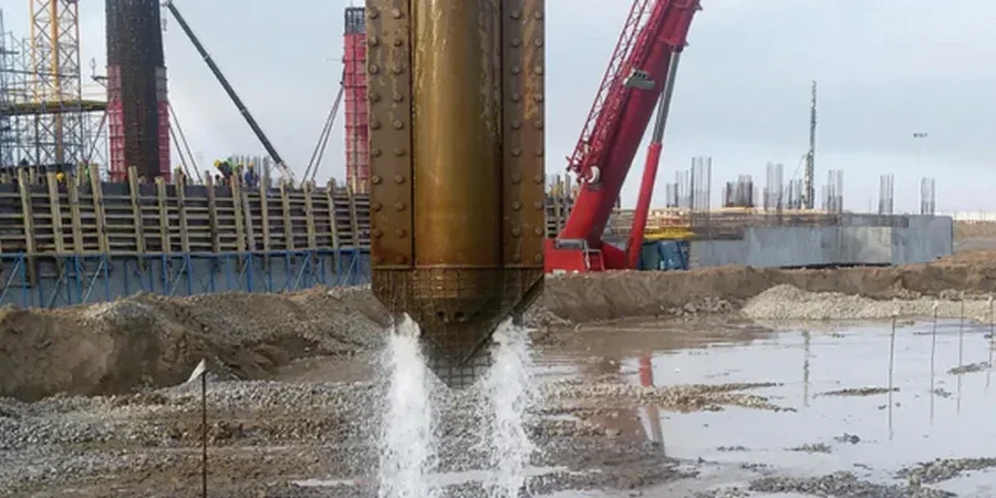
Methodology applied in Plymouth
Typical technical challenges in Plymouth
Plymouth’s post-war reconstruction and subsequent waterfront regeneration created extensive areas of reclaimed ground around Millbay, Sutton Harbour, and the naval base periphery. Much of this fill was placed without engineered compaction control, leaving a legacy of metastable soil fabric that densifies unpredictably under vibration or saturation. Heavy rainfall, common during autumn and winter months, raises the water table inside these fills and reduces effective stress to a point where even moderate construction traffic can trigger localised collapse. A vibrocompaction design prepared without a winter groundwater profile therefore underestimates the energy required to achieve target density. Further risk arises where thin clay seams, invisible on widely spaced borehole logs, act as drainage barriers during treatment and trap excess pore pressure. Our approach includes a sensitivity check on the presence of such interbeds, referencing the British Geological Survey mapping of the Plymouth Limestone and Saltash formations, and adjusts the compaction sequence to prevent hydraulic fracture in confined layers.
Our services
The design package moves from site characterisation to a fully specified treatment plan with acceptance testing protocols.
Vibrocompaction grid design
Probe spacing, pattern geometry, and penetration depth specified from grain-size analysis and in-situ density logs. Grids are optimised for Plymouth's estuarine sand profiles.
Compaction energy specification
Amperage, frequency, and hold-time curves calibrated per treatment point. Output includes real-time monitoring parameters for the rig operator.
Pre- and post-treatment CPT verification
Cone penetration testing before and after compaction to quantify density improvement. Acceptance criteria linked directly to foundation bearing capacity requirements.
Groundwater-adjusted treatment sequencing
Phased programme that accounts for tidal influence on the water table, ensuring consistent energy transfer regardless of season.
Quick answers
What soil conditions in Plymouth are suitable for vibrocompaction?
Loose granular soils with less than 15 percent fines respond well: clean sands, gravels, and mixed fills common around the Plymouth Sound and Tamar estuary. Cohesive soils with high clay content do not densify under vibration and require alternative techniques such as stone columns.
How much does vibrocompaction design cost for a typical Plymouth project?
Design fees for vibrocompaction typically range from £1,260 to £3,730 depending on the treated area, depth, and number of verification CPT soundings required. This covers grid specification, energy curves, and acceptance criteria documentation.
Which standards govern vibrocompaction design in the UK?
BS EN 1997-1:2004 (Eurocode 7) provides the overarching framework for ground improvement design, while BS 5930:2015 covers site investigation methods that feed into the design. Execution is further guided by the ICE Specification for Ground Treatment.
How is compaction performance verified after treatment?
CPT soundings at agreed grid locations compare post-treatment tip resistance and friction ratio against pre-treatment baselines. Target relative density is typically set above 70 percent, with acceptance zones defined around foundation loading areas.